- Install
- Basic operation
- Basics of programming for electronic work
- Basics of programming for Excel
- Machine learning with scikit-learn
- Visualizing data with matplotlib
- Web programming
- RPA programming
- Miscellaneous programming
- Reference
Control OLED display
You can control the OLED display of the SSD1306 or SH1106 controller.
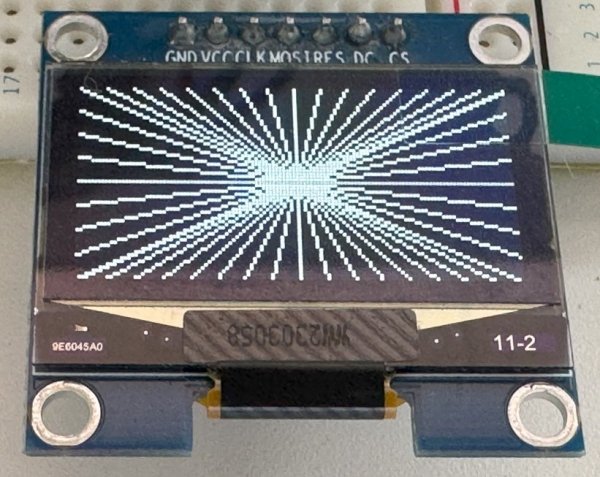
Compatible with the following types:
- SH1106 controller, 128x64 pixels
- SSD1306 controller, 128x64 pixels
- SSD1306 controller, 128x32 pixels
The connection interface supports I2C and SPI.
OLED displays for other controllers compatible with the SSD1306 may also work by configuring them for the SSD1306.
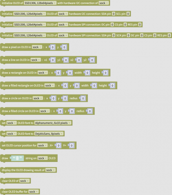
OLED-related blocks are located in the "Display" → "OLED" group.
Wiring
The OLED display connects to the microcontroller via I2C or SPI.
I2C Wiring
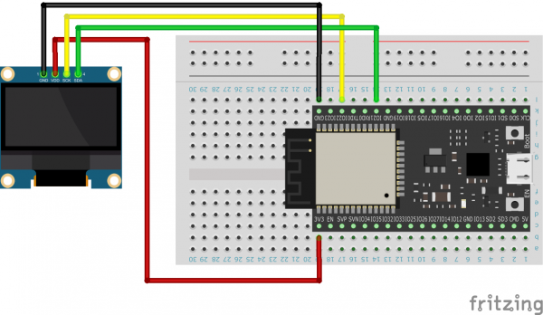
When connecting via I2C, connect the OLED display's SDA/SCL pins to the microcontroller's SDA/SCL pins, just like with a typical I2C-compatible module.
For example, if connecting an OLED display to a standard ESP32 via I2C, the wiring would be as shown in the diagram below.
SPI Wiring
When connecting via SPI, connect the OLED display's MOSI (or SDA) and SCK pins to the microcontroller's MOSI and SCK pins.
Also, connect the OLED display's DC, CS, and RES pins to any GPIO pin.
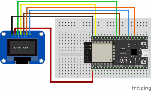
For example, if you are using a plain ESP32 (MOSI is pin 19, SCK is pin 18) and connecting DC, CS, and RES to pins 2, 4, and 5, respectively, the wiring would be as shown in the diagram below.
Initialization
Initialize the OLED display using the initialization block appropriate for your connection method.
For microcontrollers with fixed I2C and SPI pin numbers, such as the original ESP32, use an initialization block that does not specify those pin numbers.


On the other hand, for microcontrollers that allow you to freely set I2C or SPI pin numbers, you can use initialization blocks that specify those pin numbers.


Drawing
Once initialization is complete, combine blocks such as lines and circles to draw on the OLED display.
However, executing a drawing block will not immediately display anything. This will be explained later.


When drawing text, first specify the font.
The blocks for specifying fonts differ between Arduino firmware and Blinka firmware.
Also, in Arduino firmware, you cannot mix Japanese and alphanumeric characters in a block for drawing text.
Displaying the Drawing Result
Once you've finished drawing with blocks such as lines and circles, execute the block that displays the drawing result.
This will display the drawing result on the OLED display.

Clearing the Buffer
To prepare the next drawing you want to display while keeping the drawing result displayed on the OLED display, use the Clear Buffer block.

Note that the Clear Display block also clears the display on the OLED display.

Sample Program
You can download the sample program from the link below.
Sample Program for Drawing on an OLED Display
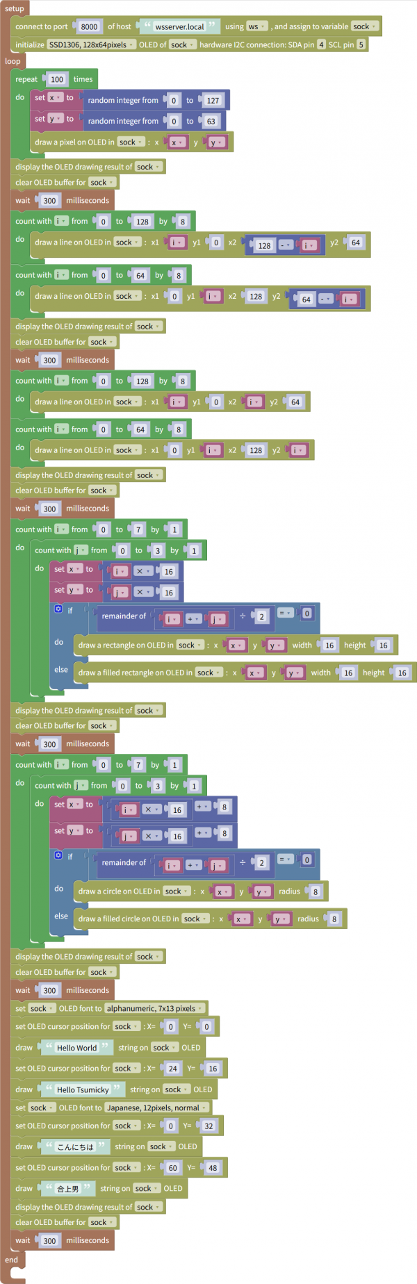
This example uses drawing-related blocks to display points, lines, squares, circles, and text.
Please modify the initialization block to suit your microcontroller.