- Install
- Basic operation
- Basics of programming for electronic work
- Basics of programming for Excel
- Machine learning with scikit-learn
- Visualizing data with matplotlib
- Web programming
- RPA programming
- Miscellaneous programming
- Reference
Digital input
Digital input can be performed from something connected to the microcontroller (switch, etc.).
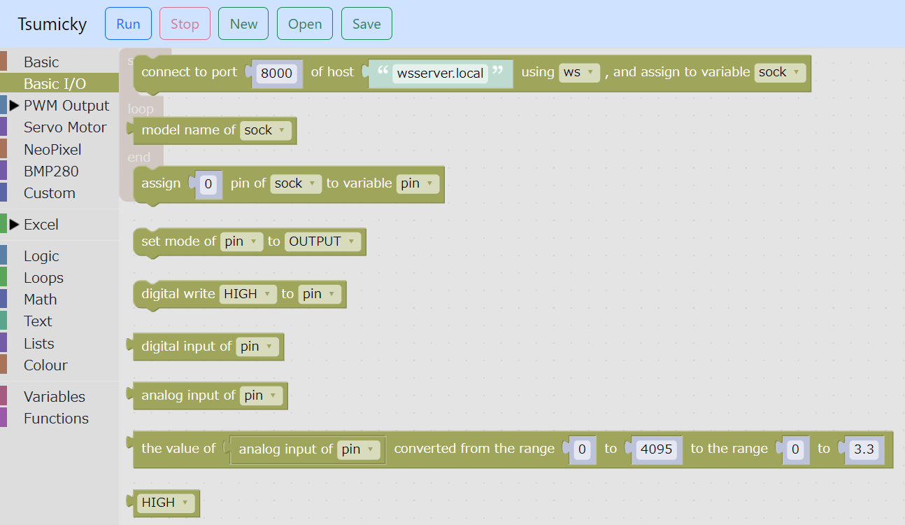
Blocks related to digital input are located in the "Basic I/O" group.
Assign pin to variable
First, use the block "Assign ... pin of ... to variable ..." to assign the output destination pin to a variable.

In the leftmost selection, select the variable to which the connected microcontroller is assigned.
In the center field, specify the pin number.
Then, in the rightmost selection, specify the variable to which you want to assign the pin.
Mode settings
Next, use the "set mode of ... to ..." block to set the mode of that pin to input.

In the choices on the left, specify the variable to which you have assigned the pin.
Then select "INPUT" from the options on the right.
Also, if you want to use the microcontroller's built-in pull-up resistor, select "INPUT_PULLUP" from the options on the right.
Read digital value
Next, use the "digital input of ..." block to obtain the digital input of that pin.

Under Choices, specify the variable to which you have assigned the pin.
Since the digital input is obtained as a return value, it can be assigned to a variable or used in an expression.
Example
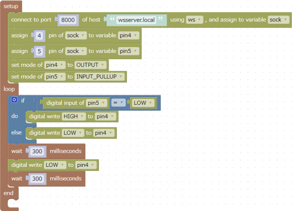
This is an example of outputting HIGH and LOW to pin 4 alternately while the input of pin 5 of the microcontroller is LOW.
If you connect a switch between the 5th board pin and GND, and also connect an LED between the 4th pin and GND, the LED will blink while the switch is pressed.
Since pin 5 uses a built-in pull-up resistor, the input value will be LOW while the switch is pressed.
This program can be downloaded from here.